Overview
Some applications require metering loads powered by two phases of a three-phase 208 Vac service:
- Single-phase 208 Vac load: sometimes this is a product designed for 240 VAC residential use that can also run from 208 Vac such as a water heater.
Generally, for this application, a 3D-240 (such as WNC-3D-240-MB) model would be used, but a 3Y-208 (such as WNC-3Y-208-MB) could also be used if neutral is available. Theoretically, only a single current transformer (CT) should be needed, because there are only two active phases, but the WattNode® WNB and WNC series generally require two CTs, because these meters uses neutral or ground as the measurement reference point.
Note that the WND series meters can measure single phase circuits using only one CT.
Issues
To save money and simplify the installation, can I use a single CT instead of two CTs?
- With residential 240 Vac circuits, a single CT should work well. You will need to double the reported power, energy, and/or current results, or pretend that the CT is rated for twice the actual rated amps. For example, if you are using a 30 A CT, use 60 A for the CtAmps that you program into the meter or use to compute scale factors.
- If there is neutral current, you must use two CTs for accurate results.
- If there is a voltage imbalance between line 1 (L1) and line 2 (L2), then this will cause a reading error of one-half the imbalance percentage. For example, if L1 = 118 Vac and L2 = 120 Vac, then the imbalance is 1.68% and the WattNode measurement error will be 0.84%.
-
-
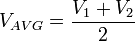
Average line voltage 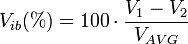
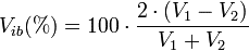
Voltage imbalance (percent) 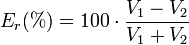
Power and energy reading error (percent)
-
- With three-phase 208 Vac circuits, you should always use two current transformers. Because the WattNode measurement reference point is neutral or ground (not L1), the voltages and currents will appear somewhat out-of-phase to the WattNode. The combined measurements from L1 and L2 will be correct, but the individual measurements for L1 and L2 may not be equal, depending on the power factor of the load, so doubling the L1 measurement may result in an incorrect result.
- This problem is especially acute for 208 Vac inverters (used with photovoltaic systems) when the inverter is not generating any electricity (at night). In this case, the output filter capacitors on the inverter present a capacitive load, so current is flowing in and out of the inverter on every AC line cycle. This results in moderate negative reactive power, but little or no real power. When monitored with a WattNode, one phase will show positive real power and the other phase will show negative real power. The sum of the two phases will result in nearly zero real power, but if you only use a single CT and double the results, you will measure substantial positive or negative real power.
- Note: In the Detailed Analysis and Correction sections below, we demonstrate that it is theoretically possible (though difficult) to compensate for only using one current transformer to monitor a two-wire 208 Vac circuit. This can only be done for certain models of WattNode and only if you have the ability to do math, including trigonometry, on the reported measurements.
Detailed Analysis
The following analysis shows the power of a two-wire 208 VAC load (or generator) and the theoretical metering results using one vs. two CTs.
 |
 |
 |
 |
 |
 |
 |
 |
 |
 |
 |
Example
The following table shows some example data assuming a constant 120 VAC line-to-neutral (208 VAC line-to-line), and a constant 10 amp current. The table shows the effect of varying power factor on the measured phase A and phase B power. In all cases, the sum of the phase A and B power matches the direct  value.
 |
 |
 |
 |
 (W) |
 (W) |
 (W) |
(W) |
 (VAR) |
 (VAR) |
 (VA) |
 (VA) |
| 120 | 10 | 1.00 | 0° | 1039.2 | 1039.2 | 2078.5 | 2078.5 | -600.0 | 600.0 | 1200.0 | 1200.0 |
| 120 | 10 | 0.71 | 45° | 310.6 | 1159.1 | 1469.7 | 1469.7 | -1159.1 | -310.6 | 1200.0 | 1200.0 |
| 120 | 10 | 0.50 | 60° | 0.0 | 1039.2 | 1039.2 | 1039.2 | -1200.0 | -600.0 | 1200.0 | 1200.0 |
| 120 | 10 | 0.00 | 90° | -600.0 | 600.0 | 0.0 | 0.0 | -1039.2 | -1039.2 | 1200.0 | 1200.0 |
Correction
It is possible to largely compensate for the errors of monitoring a two-wire line-to-line (delta) load with only one CT and one input channel of a WattNode meter using the following equations. These require models that report reactive power.
The following assumes your load (or generating source) is between phases A and B and that you are just monitoring phase A with the WattNode.
 |
Real power measured on phase A |
|
Reactive power measured on phase A |
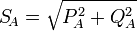 |
Apparent power measured on phase A Some WattNode models provide this value directly. |
 |
Power factor measured for phase A Most WattNode models provide this value directly. |
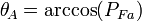 |
Voltage to current phase angle measured on phase A |
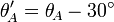 |
Corrected voltage to current phase angle |
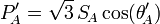 |
Corrected real power for line-to-line load |
 |
Corrected power factor |
The following table shows the correction applied to the data above, and demonstrates that the theoretical  is correct.
|
|
|
|
(W) |
(W) |
(VAR) |
(VA) |
 |
 |
 |
(W) |
| 120 | 10 | 1.00 | 0° | 1039.2 | 2078.5 | -600.0 | 1200.0 | 0.87 | 30° | 0° | 2078.5 |
| 120 | 10 | 0.71 | 45° | 310.6 | 1469.7 | -1159.1 | 1200.0 | 0.26 | 75° | 45° | 1469.7 |
| 120 | 10 | 0.50 | 60° | 0.0 | 1039.2 | -1200.0 | 1200.0 | 0.00 | 90° | 60° | 1039.2 |
| 120 | 10 | 0.00 | 90° | -600.0 | 0.0 | -1039.2 | 1200.0 | -0.50 | 120° | 90° | 0.0 |