Overview
Modscan32 is a 32-bit Windows application (Modscan64 is similar, but for 64-bit Windows) that serves as a Modbus master device for protocol testing and performing Modbus serial and TCP/IP data collection by polling at user-defined intervals down to milliseconds. It can acquire data in integer, unsigned decimal, and floating point formats. It also supports register writes. The slave response time and delay between polls are user selectable.
Continental Control Systems does sell any software products. Please contact the manufacturer directly for information on their various versions and pricing.
More details may be found at the following links:
- ModScan32 Application Description
- Download evaluation software—fully functional, limited-time free demo
Modscan32 is available in a couple of different versions. Contact WinTECH Software Design to purchase this software. The cost is $65 for the single-user basic version; or $110 for the Professional version that includes MMI (e.g. trend graphs) and OLE features for Modscan32 data access by Excel’s VBA macro language.
For more information on using Modscan32 with the WattNode® Modbus® meter see WNC Modbus Customer Questions.
Pros
- Supports Modbus/TCP, Remote Telnet Server (for Ethernet/RS-485 SDAs) and a variety of other connection types (including Telnet) as well as direct serial port (COM port) connections.
- Has optional handshake line control which may be needed for older RS-232/RS-485 adapters used on legacy PC serial ports that don’t handle RS-485 bus driver control automatically.
- Has a “hex dump” display mode which is useful for trouble-shooting communications problems.
- It can be quickly set up to read a range of registers of the same type (vs. Ocean Controls approach of setting up individual tags which is more tedious and time-consuming).
Cons
- Modscan32’s Point Type selection defaults to “Coil Status” which requires switching it to “Holding Register” before a WattNode meter’s register can be polled.
- Modscan32 is a tool intended mainly for engineers and IT folks who are familiar with the basics of protocols like Modbus.
- Captured text files are not in standard CSV (Comma Separated Values) format. The non-standard data format requires using Excel’s Import Wizard which takes more steps. However, there is a work-around for this (see csv.exe below).
- Poor trend graphing capability. Difficult to set up and change.
- When trying to change a value, the focus doesn’t start in the value text box, requiring an extra click.
- When displaying floating point values, if the window isn’t tall enough, Modscan32 displays multiple columns, but the text from one column overlaps the next.
- When displaying floating point values, Modscan32 displays blank lines between every other value.
- Runs only on Windows. No Linux or Apple OS version is available.
Quick Start Guide
This section describes how to connect and configure a WattNode meter with Modscan32, set the CtAmps, and make some basic measurements.
It also discusses how to use ModScan32 to communicate with WattNode meters via the two most common types of SDA (Serial Device Adapter):
- A USB/RS-485 adapter.
- An Ethernet/RS-485 adapter.
ModScan32 is for polling and recording data readings from slave devices that use the Modbus communications protocol. It can also write to registers to configure settings in Modbus slaves. The free demo version can be useful for isolating the cause of problems when a customer is using another third-party Modbus master program that is misconfigured or that has a software bug by allowing them to compare the readings acquired with their software versus the readings acquired with ModScan32. ModScan32 can also serve as a simple data logger for capturing data in text files. Since the demo version can be freely distributed, an installer can use it for the minute or two that it takes to configure the CT amps ratings via the WattNode meter’s CtAmps registers and to verify that the Modbus communications is working.
ModScan32 runs on most versions of MS Windows, including Windows XP. ModScan32 can communicate with the Modbus WattNode meter using SDAs that support RS-48.
WinTech’s time-limited free demo version of ModScan32 runs for a couple of minutes, which is long enough to configure a WattNode meter’s CtAmps registers. To eliminate the time limit, the demo can be registered by entering a license key obtained from WinTech. As of Q3 2009, the basic version costs $65 and the Pro version costs $110. Both versions of ModScan32 support viewing and updating numeric register values and capturing data to text files that can be imported into spreadsheet programs like Excel. The Pro version includes additional features that support viewing the data as trend lines on simple graphical charts and exporting data to OLE client programs. Installing it is as simple as downloading the free demo Modscan32.zip file and copying its contents into a folder named, “C:Modscan32”.
How to use Modscan32 with a COM port to Configure the WattNode meter’s CT Amps Settings
The installation details for USB/RS-485 adapters varies depending on the particular model but the main steps are the same regardless of model.
There is a video-only (no sound-track) that illustrates this procedure at http://www.youtube.com/watch?v=QRiGhUDisRg :
- Connect power supply if needed. Note that most USB/RS-485 adapters are powered by the USB host and do not require an external power supply.
- Insert the adapter. Windows “New Hardware Device Wizard” should appear and prompt for the location of the device driver files which are usually on the software distribution CD that came with the adapter.
- After following the prompts, if the adapter driver installed correctly, you should see it listed under the Windows Device Manager’s Ports (COM & LPT) list. Usually it will include “RS-485” in the name. Note the COM port number that Windows assigned to the device.
- Use Windows Explorer to view the folder where Modscan32 is installed and start Modscan32 by double clicking the Modscan32.exe executable.
- Once Modscan32 starts up a “Modsca1” document window should appear. Enter the WattNode meter’s slave address (set with the DIP switches) in the “Device Id” box. For example if the meter’s DIP switches 2 to 7 are off and 1 is on, enter a value of 1.
- Next specify that you want to read the CT Amps registers: Under “Modbus Point Type”, select “Holding Register”. Under “Address” enter “1603”. Under “Length” enter “4”. This selects the global CT Amps register CtAmps and the CT Amps registers for each of the three phases (CtAmpsA, CtAmpsB, and CtAmpsC).
- Select “Connection->Connect” and under “Connect Using”, select the COM port number of your adapter and make sure the baud rate matches the WattNode meter’s (9600 if DIP switch 8 is off; 19200 if it is on). No hardware flow control is needed for most USB/RS-485 adapters which have the “auto-enable” feature.
- Click the “Protocol Selections” button and make sure that the “Transmission Mode” is set to “RTU”. The “Slave Timeout” should be “1000 ms”. and for the “Delay Between Polls”, 500 ms. is a reasonable poll rate.
- Close the dialogs by clicking the “OK” button and at that point, Modscan32 should start polling the WattNode Modbus meter. The “Number of Polls” will start incrementing and if the RS-485 interface is properly connected to the adapter, the “Number of Valid Slave Responses” should increment at the same rate.
- To set the CT Amps settings to different values for each of the three phases, double-click on the displayed register which will pop up a “Write Register” dialog that allows you to enter the new value. Enter the CT rating in amps and click “Update”. The dialog will close and the displayed value of the corresponding CT Amps register should change accordingly.
- If the CT rating is the same for all three phases, you can set all three to the same value at once by writing to the Global CT Amps register (1603).
- When you are done you can select “File->Save As” and specify the file name “CtAmps” to save the changes you made so the next time you run Modscan32, you can select “File” and click on “CtAmps” so you don’t have to re-enter the same register addresses etc. again.
How to Read All WattNode Registers Using Preconfigured Modscan32 Document Files
Since there is no universal standard for mapping Modbus register addresses onto specific slave device readings (because the Modbus standard only specifies the low-level communications data transport layer, not the high-level application layer or data types), some customization is required in order to specify which data registers should be polled from a specific slave device and how the data should be formatted. ModScan32 saves this configuration data in special “documents”, where each document corresponds to a continuous series of Modbus holding registers. Each document window displays register data of the same type and format (floating point or 16-bit integer etc.).
To save time in configuring Modscan32, preconfigured ModScan32 documents are available from CCS in a ZIP archive file named, “Modscan32ForWattNode.zip“. These files are preconfigured for acquiring the specific registers containing the WattNode meter data and assume that the meter is assigned a slave address of 1 and that its baud rate is set to 19200 (i.e. the meter’s DIP switches 1 and 8 are on, and 2 to 7 are off). The WattNodeAutoStart.tst Auto-start configuration file assumes that the USB/RS-485 adapter is assigned to the PC’s COM10 serial port (this can easily be changed as described below). The contents of the Modscan32ForWattNode.zip file should be copied to the same folder, “C:Modscan32”, that you created with Windows Explorer when you installed Modscan32.
There are seven custom configuration files for the WattNode meter:
- Ms32frm.cfg ” This file tells Modscan32 to automatically load the configuration contained in the WattNodeAutoStart.txt file at start-up.
- WattNodeAutoStart.tst – This is the Auto-start configuration file that tells Modscan32 which COM port the meter is connected to and which documents to automatically open when it starts up.
- WattNodeBasicFloatOutputs – This Modscan32 document displays energy, power and voltage float registers 1001 to 1034.
- WattNodeAdvancedFloatOutputs – This Modscan32 document displays advanced energy, power and demand float registers 1112 to 1176.
- WattNodeConfiguration – This Modscan32 document displays configuration integer registers 1601 to 1621.
- WattNodeCustomerDiagnostics – This Modscan32 document displays customer diagnostic integer registers 1707 to 1722.
- WattNodePowerTrendGraph – This Modscan32 document displays the phase A, B, C and Demand power float registers (1011, 1013, 1015 and 1169) as red, green, blue and violet traces, respectively on a trend graph.
After copying the WattNode meter configuration files from the Modscan32ForWattNode.zip file into the same C:Modscan32 folder that you installed the Modscan32 program (overwriting the existing configuration files), you can launch Modscan32 by double-clicking on Modscan32.exe. Upon launching, Modscan32 will display some “Registration” dialog boxes. After clicking “OK” to each dialog, Modscan32 will then try to connect to the meter and if successful, it will display and update the five documents listed above with new data every 2 or 3 seconds.
If your USB/RS-485 adapter has been assigned to a different COM port then an error message will appear that says, “Connection Failed!”. In that case, you need to tell Modscan32 which COM port to use by clicking the Connection menu bar item and selecting the “Connect” item from the list. A dialog box that appears with a “Connect Using:” list box that allows you to select the proper COM port (Note: The Windows Device Manager applet displays all serial COM ports under the Ports device group). After you’ve selected the right port, click OK and Modscan32 should then start polling the WattNode meter and updating the displayed documents after a few seconds.
If your meter uses a CT rated for other than the default of 5 amps, you can reconfigure it for the proper CT rating by clicking on the WattNodeConfiguration document view. Integer register 1603 is the global CT amps register which allows you to set the CT rating for all three phases if they all have the same rating. In cases where differently rated CTs are used on each phase, registers 1604, 1605 and 1606 allow assigning each CT amps rating for phases A, B and C respectively. If any phase inputs are not used and are left unterminated (no shorting wire) then they can cause small but unwanted energies to be accumulated due to stray electrical fields. This can be prevented by setting their CT amps register to zero, including the global CT amps register (Note: The phase LEDs may still occasionally flash red but no energy is accumulated if the CtAmps register is zero).
To change the value of a register, double-click the displayed register value and a dialog box will appear that lets you enter the new value. After entering the new value, click the “Update” button and the new setting will be written to the meter.
Modscan32 can log the data readings for any of the displayed documents into text files consisting of space-separated values. This is done by clicking on the document to bring it to the foreground and then selecting “Setup” from the menu bar and then “Text Capture”. A “Save As” dialog will appear that allows you to specify the text file name and location. After specifying the file name, another dialog will appear that lets you choose how often to archive the data. To stop collecting WattNode data, select “Setup” and then “Capture Off”. Note that you can specify a different data file name and start and stop logging data separately for each document. Since the data is captured as a text file, you should use the “txt” file name extension for data file names. To import a captured text file with Excel, select “Open” and browse to the Modscan32 folder and select Excels dialog option containing “*.txt” from the “Files of Type” list box. A dialog will appear that lets you tell Excel exactly how to import the data. Select the “Delimited” option and click “Next”; then check the “Space” box and Excel presents you with an example of the data that permits selecting columns you don’t want to import (e.g. the redundant date fields). After you click “Finish” the data will be imported into the spreadsheet.
If you’re familiar with how to run Windows console applications, you can use a utility called csv.exe (included in the zip file below) that converts from Modscan32’s data format into standard comma-separated values (CSV) format that can be pulled into Excel without using the Excel data import wizard. The csv.exe utility processes a data file you previously captured with Modscan32 and converts it to CSV format that Excel automatically recognizes.
Whenever you change the Modscan32 “Connection” settings you should save them to the WattNodeAutoStart.tst Auto-start configuration file by selecting “Connection”, “Auto Start”, “Save Config” and selecting the WattNodeAutoStart.tst file name. This way, the next time you launch Modscan32, it will be able to restore the same communications connection automatically.
The appearance of the WattNodePowerTrendGraph document can be customized by right-clicking it. A Trend Chart Properties dialog will appear that lets you customize the trace (or pen) colors and assign a data register source to a particular trace. Individual traces can be enabled or disabled by clicking the corresponding pen button and checking or un-checking the Enabled box. The register address is entered in the “Point Address:” field. The format of the data under the “Format” list box should match the type of register you want to assign to the trace. It is easiest to use the WattNode float (vs. integer) registers for trend graphs (and also for capturing data readings to text files). After making changes to the trend graph you should save them by selecting “File” and “Save” so it will reappear the same way the next time you start Modscan32.
To add a new Trend Chart, click “File”, “Custom Form” and “Create”. Then use the mouse to define a rectangular region for the MMI object in the document that appears. Click on the point where you want the upper left corner to appear and while holding down the mouse button, drag the cursor to the lower right hand corner. A “Custom Display” dialog box will then appear that lets you select the “Simple Trend Chart”. You can then right click the resulting chart to customize the “Pen” attributes that determine the displayed traces.
How to use Modscan32 with an Ethernet/RS-485 Serial Device Adapter
The following describes how to connect to a WattNode meter using an Ethernet/RS-485 SDA. You can ignore this section if you are using a USB/RS-485 adapter. Since the WattNodeAutoStart.txt Auto-start configuration file was set up for a USB/RS-485 adapter on the COM10 port, the “Connection Failed!” error message will appear when you launch Modscan32. To fix this, select “Connect” and under the “Connect Using:” list box, select “Remote TELNET Server” and enter the TCP/IP address and port of your SDA in the “IP Address:” and “Service Port:” boxes, respectively. These values should match the ones you assigned to your SDA. Refer to your SDA manual for the procedure for assigning the SDA address, port and serial communications parameters. This is usually done with a Web browser but the exact details vary depending on SDA make and model.
Summary
Modscan32 is a simple but useful program and the price is reasonable compared to most SCADA or Data Logger software. If you only need to use it for a minute or two for assigning the CtAmps configuration registers then the free demo version should be adequate. Modscan32 will work with any Modbus slave device that conforms to the Modbus communications protocol (see http://www.modbus.org). By using it in conjunction with the Modscan32 configuration files provided by CCS, it provides a quick, vendor-neutral way to verify that a power monitoring installation with Modbus WattNode meters is working properly.
The figure below shows how Modscan32 presents the WattNode meter data in both numeric and graphic form:
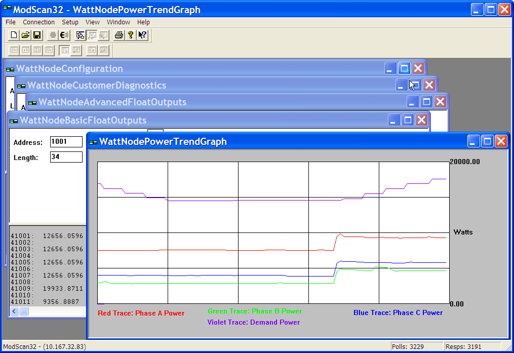
The WattNode configuration files for Modscan32 are contained in a single ZIP file: Modscan32FilesForWattNode.zip
See Also
Keywords: Modscan, Win-Tech, RS485, EIA485, EIA-485