| Product Discontinued Information is for legacy purposes |
True RMS – AC Power Measurement for LonWorks® Networks
The WNA Lonworks Output WattNode has been replaced with the WattNode Plus for LonWorks
Download a datasheet or a manual (PDF).
The WattNode® for LonWorks combines three true RMS instruments in one: watt meter, watt-hour meter and demand meter. Typical applications include energy monitoring, performance verification and sub-metering where accuracy at reasonable cost is essential.
Through the LonWorks network, the WattNode communicates power (watts), energy (kilowatt-hours), demand and alarm conditions.
Easy installation saves you time and money. The WattNode is small enough to fit entirely within a standard electrical panel and the screw terminals unplug for easy wiring. A twisted pair of wires is used to create the network. The WattNode complies with the LonMark Interoperability Guidelines, Version 3.0. These guidelines ensure a standard interface so that the WattNode may be rapidly configured to communicate with other nodes on the LonWorks network.
The complete WattNode family measures 1, 2 or 3 phases in delta (3 phase, 3 wire) or wye (3 phase, 4 wire) configurations. With voltage ratings from 120 to 600 VAC and current transformer (CT) ratings from 5 to 3000 amps, there is a WattNode combination to meet nearly all of your AC power measurement requirements.
Accuracy of the WattNode is 0.5% of reading over a wide range of power factor and harmonic content. The WattNode measures true RMS power even with leading or lagging power factor and chopped or distorted waveforms. This makes the WattNode ideal for monitoring motors and pumps controlled by variable speed drives.
To assure reliability and accuracy, each WattNode is tested and calibrated by a custom, automated production system. A key part of the production process is calibration with NIST traceable standards. To assure the initial calibration accuracy is maintained, the WattNode has been designed with fixed, precision resistors, not potentiometers, in its measurement circuit.
Our safe CTs, with integral burden resistors, produce a voltage proportional to the load current. At rated current the voltage is only 0.333 VAC. Split core CTs quickly install on existing wiring and solid core CTs can prevent tampering. Bus bar CTs are available in a variety of standard sizes, plus custom designs up to 10″ x 10″ (254mm x 254mm) and 4000A.
Features
- Three Measurements in One Instrument
- Power (watts, kilowatts)
- Energy (watt-hours, kilowatt-hours)
- Demand and peak demand (watts, kilowatts)
- Complies with LonMark Interoperability Guidelines – Easy to integrate into network.
- Output: W, kW, WH, kWh, Peak Demand – Multiple measurements in one unit.
- Small size – Can be installed in existing service panels or junction boxes.
- Uses safe CTs – Output limited to low voltage by integral burden resistor.
- Line powered – No external supply required.
- Detachable terminal blocks – Easy to install and remove.
Specifications
Measurement Configurations
- Single phase: 2 or 3 wire
- Three phase: 4 wire
- Three phase: 3 wire
Quantities Measured
- Energy in WH or kWh
- Instantaneous power in W or kW
- Demand (power) in W or kW
- Peak demand (billing demand) in W or kW
- Alarm conditions (user defined):
- peak demand
- instantaneous power
Quantities Retained During Power Loss
- Accumulated energy
- Peak demand
- Alarm set points
- Operating range configuration
LonMark Interoperability
- Certified to meet version 3.0 of the LonMark Interoperability Guidelines
- Uses Standard Network Variable Types (SNVTs):
- Electrical Energy: SNVT_elec_kwh, SNVT_elec_whr_f
- Electrical Power: SNVT_power, SNVT_power_kilo, SNVT_power_f
- Configuration: LonMark standard configuration SNVTs
- Installation: Service pushbutton and service LED
Configuration Control
- Configure operating ranges
- Reset accumulated energy to zero
- Reset peak demand to zero
- Set alarm set points
Electrical
- Line powered
- FCC Class A
- Operating Voltage Range: ±20% of nominal
- Power Line Frequency: 50 or 60 Hz
- CT Input: 0 – 0.5 VAC operating, 3 VAC maximum
Accuracy
- 0.45% of reading + 0.05% of full scale through 25th harmonic
Environmental
- Operating Temperature: -30° to 60°C
- Humidity: Up to 90% RH (non-condensing)
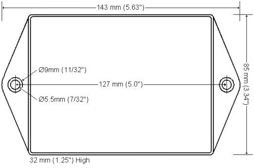
WattNode Dimensions
Mechanical
|
 |
Models
| Model | VAC Phase to Neutral |
VAC Phase to Phase |
Phases | Wires |
|---|---|---|---|---|
| WNA-1P-240-FT10 WNA-1P-240-TP78 |
120 | 240 | 1 or 2 | 2 or 3 |
| WNA-3Y-208-FT10 WNA-3Y-208-TP78 |
120 | 208-240 | 1, 2 or 3 | 4 |
| WNA-3Y-400-FT10 WNA-3Y-400-TP78 |
230 | 400 | 1, 2 or 3 | 4 |
| WNA-3Y-480-FT10 WNA-3Y-480-TP78 |
277 | 480 | 1, 2 or 3 | 4 |
| WNA-3Y-600-FT10 WNA-3Y-600-TP78 |
347 | 600 | 1, 2 or 3 | 4 |
| WNA-3D-240-FT10 WNA-3D-240-TP78 |
N/A | 208-240 | 2 or 3 | 3 |
| WNA-3D-480-FT10 WNA-3D-480-TP78 |
N/A | 480 | 2 or 3 | 3 |
The transceiver suffix is either:
- -TP78, twisted pair 78Kbps transceiver
- -FT10, free topology 78Kbps transceiver
The delta models, WNA-3D-240-xxx and WNA-3D-480-xxx, are used only when neutral is not present.
Datasheet, Manual, XIF File, and Application Notes
- Download a datasheet (PDF)
- Download or view the Manual: User’s Guide (PDF)
- Download XIF (external interface) File WN_FT10.XIF WN_TP78.XIF
- See a list of Application Notes