|
Product Discontinued Information is for legacy purposes Replaced by WND-WR-MB |
NOTICE:
As of January 1, 2022, all standard (WNC) and revenue-grade (RWNC) Modbus meters have been replaced by the new WND-WR-MB WattNode Wide-Range Modbus meter.
For revenue-grade ANSI C12 applications, purchase Calibration Certificates (WN-CAL-Cert) for each revenue meter and use with Accu-CT revenue grade class C0.6, C0.3, or C0.2 current transformers.
WattNode® WNC Power Meters for Modbus® – Downloads
- WattNode WNC Power Meter for Modbus
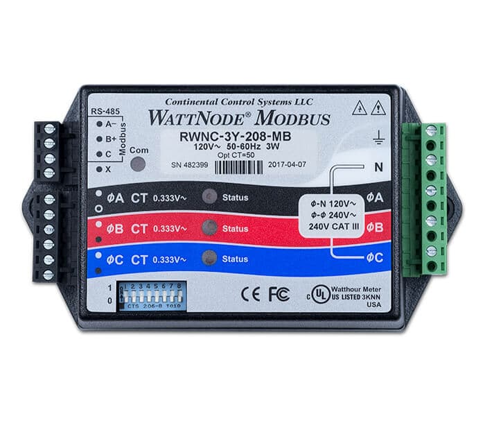
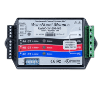
- WattNode RWNC Revenue Power meter for Modbus
Sales Brochure
- WattNode Revenue Line Card (PDF, 1 page)
- WattNode Revenue Brochure (PDF, 1 page)
Manuals, Technical Documents, and JAR File for WNC Power Meters
Support Links
- Reference Manual (PDF, 61 pages) – for both WattNode Modbus and WattNode Revenue for Modbus Models
- Install Guide (PDF, 16 pages) – for both WattNode Modbus and WattNode Revenue for Modbus Models
- WattNode Revenue for Modbus – Manual Supplement 23 (PDF, 2 pages)
- Engineering Specifications (DOC, 1 page)
- Register List (XLS, 87 kb)
- 3D Envelope Model (PDF, 115 kb)
- Application Notes
- Support Articles
- Tridium JACE Modbus (Jar File) – See also Niagara AX JACE with WattNode Modbus
Firmware Updates
The WattNode power meters for Modbus production firmware version is periodically updated. The firmware cannot be field upgraded, so the WattNode power meter must be returned to the factory for firmware updates. There is a nominal charge for firmware updates unless they are needed to fix a bug under warranty. Unless you are experiencing problems, there is generally no reason to update the firmware.
See WNC Series WattNode Modbus Firmware Versions for the full list of versions.
Modbus is a registered trademark of Schneider Electric USA, Inc.
Description
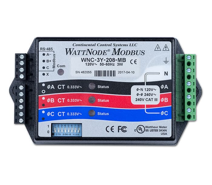
The WNC Series WattNode® for Modbus® kilowatt hour (kWh) energy and power meter communicates over an EIA RS-485 network, measures 1, 2, or 3 phases with voltages from 120 to 600 volts Vac and currents from 5 to 6,000 amps in delta (phase to phase) and wye (phase to neutral) configurations.
Diagnostic LEDs
Our diagnostic LEDs provide a per-phase indication of power (green flashing) and negative power (red flashing) to help troubleshoot connection problems, like reversed CTs, or excessive line voltage. The WattNode Modbus meter also has a red/yellow/green communication LED to indicate traffic, configuration problems, bus contention and other conditions. See the manual for full descriptions.
Measurements
- Supports floating point and integer registers
- True RMS Power: Watts (Phase A, B, C, and sum of all phases)
- Reactive Power: VARs (Phase A, B, C, and sum of all phases)
- Power Factor: (Phase A, B, C, and sum of all phases)
- True RMS Energy: Kilo-Watthours kWh (Phase A, B, C, and sum of all phases)
- Reactive Energy: kVAR-hours (All Phases)
- AC Line Frequency
- RMS Voltage: (Phase A, B, C)
- Computed RMS Current: (Phase A, B, C)
- Demand
- Peak Demand
WattNode Modbus—Features
 |
 |
||
| WNC Model | RWNC Model | Features | |
|---|---|---|---|
| Meets ANSI C12.1 for use in revenue grade metering | |||
| Small form factor for easy installation inside most electrical panels, see a sample WattNode Modbus Installation |
|||
| Pluggable screw terminals for easy wiring | |||
| Nominal accuracy 0.5% (see Installation and Operation Manual for details) | |||
| True RMS power even with leading or lagging power factor and chopped or distorted waveforms | |||
| Measure variable speed motor drives used in HVAC, refrigeration, and pumping systems | |||
| Safe CT’s (Current Transformers), output 0.333 Vac at rated current. | |||
| UL, cUL Listed – Designed and tested for safety and use throughout North America and the European Union. | |||
| Assembled in USA, qualified under the Buy American provision in the American Recovery and Reinvestment Act of 2009 (ARRA). | |||
| Five year warranty |
WattNode® Power Meter for Modbus® – Specifications
Modbus Communication
- Protocol: Modbus RTU (binary)
- Baud Rates: 2,400, 4,800, 9,600,19,200, and 38,400 baud
- Duplex: Half (two-wire plus common)
- Parity (default): N81 (no parity, eight data bits, one stop bit)
- Modbus Buffer: 256 bytes
- Response Time (typical): 5 to 25 milliseconds
EIA RS-485 Interface
- Driver Output Voltage (Open Circuit): ± V maximum
- Driver Output Voltage (54Ω load): ± 1.5 V minimum
- Driver Output Current (54Ω load): ± 60 mA typical
- Driver Output Rise Time (54Ω || 50 pF load): 900 nS typical
- Receiver Common-Mode Voltage Range: –7 to +12 Vdc maximum
- Receiver Sensitivity: ±200 mV
- Receiver Bus Load: 1/8 unit load
Electrical
- Line powered
- Operating Voltage Range: –20% to +15% of nominal
- Power Line Frequency: 50 or 60 Hz
- CT Input: 0.333 Vac nominal, 0 to 0.5 Vac operating, 3 Vac maximum
Measurement Configurations
Models available for:
- Single phase: two or three wire
- Three phase: four wire wye
- Three phase: three wire delta
- Three phase: four wire delta
Accuracy
WattNode Modbus
- 0.5% nominal (see WNC Modbus Reference Manual for details)
WattNode Revenue Modbus
- 0.5% nominal (see WNC Modbus Reference Manual for details)
- Meets the accuracy requirements of the ANSI C12.1 standard when used with CCS CTs rated for IEEE C57.13 class 0.6 accuracy (see Revenue Grade CTs).
- Models RWNC-3Y-208-MB, RWNC-3D-240-MB and RWNC-3Y-480-MB are certified by MET Laboratories to meet ANSI C12.1. MET Labs is a nationally recognized testing laboratory (NRTL).
Regulatory
- FCC Class B, EN 55022 Class B
- UL and cUL Listed (UL 61010-1), file number E312220
- CE Mark and RoHS Declaration of Conformity
- Immunity: EN 61326: 2002 (Industrial Locations)
Environmental
- Operating Temperature: -40°C to +75°C (-40°F to 167°F)
- Altitude: Up to 2000 m (6560 ft)
- Operating Humidity: 5 to 90% relative humidity (RH) up to 40°C, decreasing linearly to 50% RH at 55°C.
- Pollution: POLLUTION DEGREE 2 – Normally only non-conductive pollution; occasionally, a temporary conductivity caused by condensation must be expected.
- Indoor Use: Suitable for indoor use.
- Outdoor Use: Suitable for outdoor use when mounted inside an electrical enclosure (Hammond Mfg., Type EJ Series) that is rated NEMA 3R or 4.
Mechanical
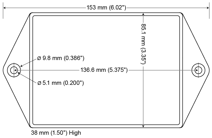
Case Dimensions
(Click on the image for a larger view.)
- Enclosure:
- High impact, ABS plastic
- Flame Resistance Rating: 94V-0, IEC FV-0
- Size: 5.63 × 3.34 × 1.5 in. (143 × 85 × 38 mm)
- Weight: 10.8 oz (305 g)
- Connectors: Euroblock style pluggable screw terminal blocks
- Green: 22 to 12 AWG (0.32 to 2.5 mm2), 600 V
- Black: 22 to 12 AWG (0.32 to 2.5 mm2), 300 V
- Screw torque 4.4 lbf⋅in (0.5N⋅m)
Modbus is a registered trademark of Modbus Organization, Inc.
WattNode® Modbus® – Model Part Numbers
 |
 |
||||
| Standard Model | Revenue Model | Vac Line to Neutral | Vac Line to Line | Electrical Service Types | Neutral Required |
|---|---|---|---|---|---|
|
WNC-3Y-208-MB
|
RWNC-3Y-208-MB
|
120 | 208-240 | Single-Phase 120V with neutral Single-Phase 3-Wire 120/240V 3-Phase 4-Wire Wye 120/208V |
Yes |
|
WNC-3Y-400-MB
|
RWNC-3Y-400-MB
|
230 | 400 | Single-Phase 230V with neutral 3-Phase 4-Wire Wye 230/400V |
Yes |
|
WNC-3Y-480-MB
|
RWNC-3Y-480-MB
|
277 | 480 | Single-Phase 277V with neutral 3-Phase 4-Wire Wye 277/480V |
Yes |
|
WNC-3Y-600-MB
|
RWNC-3Y-600-MB
|
347 | 600 | Single-Phase 347V with neutral 3-Phase 4-Wire Wye 347/600V |
Yes |
|
WNC-3D-240-MB
|
RWNC-3D-240-MB
|
See below | 208-240 | Single-Phase 208V (No neutral) Single-Phase 240V (No neutral) Single-Phase 3-Wire 120/240V 3-Phase 3-Wire Delta 208V–240V (No neutral) 3-Phase 4-Wire Wye 120/208V |
|
|
WNC-3D-400-MB
|
RWNC-3D-400-MB
|
See below | 400 | 3-Phase 3-Wire Delta 400V (No neutral) 3-Phase 4-Wire Wye 230/400V |
|
|
WNC-3D-480-MB
|
RWNC-3D-480-MB
|
See below | 480 | 3-Phase 3-Wire Delta 480V (No neutral) 3-Phase 4-Wire Wye 277/480V |
- Voltage Ranges listed in table are -20% to +15% of nominal. For 3D-240 models, this is -20% of 208 Vac (166 Vac) to +15% of 240 Vac (276 Vac). Operating Frequencies: 50/60 Hz
- Delta models (3D in part number) work either with or without a neutral connection, but require a line-to-line voltage connection for operating power.
- Add 10% to the indicated price for any option or valid combination of options. For a list of available options see the Modbus Options tab.
- Models RWNC-3Y-208-MB, RWNC-3D-240-MB and RWNC-3Y-480-MB are certified by MET Laboratories to meet ANSI C12.1. MET Labs is a nationally recognized testing laboratory (NRTL).
WattNode® Modbus – Options
The WattNode® Modbus® and WattNode Revenue Modbus meter is available with several factory options at an additional charge. See the WattNode Modbus manual (pdf) for more information and details about the registers mentioned below.
These options apply to the following two families of WattNode meters for the Modbus protocol:
- WattNode Modbus
- WattNode Revenue for Modbus
General Options
- Option CT=xxx – Pre-assign xxx as the global CtAmps value.
- Except on Revenue models, this can be field configured or overridden using the CtAmps register.On WattNode Revenue models, Option CT will be factory-set to match the CTs specified when ordering the meter.
- Option CT=xxx/yyy/zzz – Pre-assign xxx to CtAmpsA, yyy to CtAmpsB, and zzz to CtAmpsC.
- Except on Revenue models, these can be field configured or overridden using the CtAmpsA, CtAmpsB, and CtAmpsC registers.
Communication Options
- Option EP – Factory configure the Modbus RS-485 communications to default to even parity (E81)
- This can be field configured using the ParityMode register if you have meters that were ordered without this option and you need even parity. This can be overridden or turned off in the field by changing the the ParityMode register.
- Option 19K – Factory configure the RS-485 communications 19,200 baud.
- This can be changed in the field by switching the baud rate DIP switch, or by writing to the Baud register. If you write “0” to the BaudRate register, then the DIP switch setting will control the baud rate.
- Option 38K – Factory configure the RS-485 communications to 38,400 baud. Position 8 of the DIP switch will be ignored.
- This can be changed in the field by writing a new value to the BaudRate register. If you write “0” to the BaudRate register, then the DIP switch setting will control the baud rate.
- Option TCP-RTU – Configure the communications to the Modbus TCP-RTU protocol option for use with RS-485 to Ethernet converters (serial device adapters).
- This can be field configured or disabled with the ModbusMode register.
- Option AD – Factory configure the Modbus address.
- This can be changed in the field by by writing a new address to the Address register. If you write 0 (zero) to the Address register, then the DIP switch setting will specify the Modbus address.
Note: All WattNode Modbus meters can have their communication settings restored to factory shipped values by setting all DIP switch positions to “0” for ten seconds. If an communication option has been ordered, the meter will restore to include the settings from any options.
X Terminal Options
These options all utilize the X (auxiliary) terminal on the “MODBUS” connector:
- Option X5 – Provides 5 Vdc at up to 60 milliamps between the C (common) and X (5V) terminals.
- Option IO – Provides a digital input (level sensing and pulse counting) or output (for load shedding and other applications) on the X terminal.
- Option SSR – Provides a solid-state relay (contact closure) output between the X and C terminals for load shedding and other applications.
Special Options
Contact the factory about the following special options:
- Option 232 – Provide RS-232 I/O in place of RS-485.
- Option TTL – Provide 5V TTL UART I/O in place of RS-485.
Reading the Options Register
An alternative to the option information registers (see above), is the Options register 1709 which gives options as a bit field. The Options register can only be set at the factory, but many of the settings applied by options can also be field configured using the communication registers (Address, Baud, ParityMode, etc.).
The table below shows how to interpret the value read back from the Options register:
| Bit | Binary Format |
Decimal Format |
Hex Format |
User Configurable |
Option Feature(s) |
|---|---|---|---|---|---|
| 0 | 1 | 1 | 1 | Yes | Option TCP-RTU |
| 1 | 10 | 2 | 2 | Yes | Option EP |
| 2 | 100 | 4 | 4 | Yes | Option 19K, Option 38K |
| 3 | 1000 | 8 | 8 | No | Option 232 |
| 4 | 1 0000 | 16 | 10 | No | Option TTL |
| 5 | 10 0000 | 32 | 20 | Yes (see note 1) | Option CT |
| 6 | 100 0000 | 64 | 40 | No | Option X5 |
| 7 | 1000 0000 | 128 | 80 | Yes (see note 2) | Option IO |
| 8 | 1 0000 0000 | 256 | 100 | No | Option SSR |
| 9 | 10 0000 0000 | 512 | 200 | Yes | Option AD |
| 10 | 100 0000 0000 | 1024 | 400 | No (see note 3) | RWNC revenue grade model with Option CT=NNN (see note 3) |
| 11 | 1000 0000 0000 | 2048 | 800 | No (see note 3) | RWNC revenue grade model with settings locked (see note 3) |
| 12 | 1 0000 0000 0000 | 4096 | 1000 | No | LEDs disabled |
| 13 | 10 0000 0000 0000 | 8192 | 2000 | No | DIP switch disabled |
| 14 | 100 0000 0000 0000 | 16384 | 4000 | No | Fast (200 millisecond) power update rate |
For each option that applies there is a bit (or binary digit) set in the Options register. When only a single option applies, the register value represents the decimal weight for that bit. If multiple options are selected, then the bit values add together. For example, if you order Option 38K (bit 2 set = 4 decimal or 100 binary) with Option TTL (bit 4 set = 16 decimal or 10000 binary), the Options register will read back a value of 20 decimal (both bits 2 and 4 set = 14 hexadecimal or 10100 binary).
Where the meter has many options, it is easiest to determine which options apply by converting the Options register value from a decimal integer into a binary number. The binary number format indicates each option as a separate bit which is represented as either a “1” (one bit, which indicates the option is present) or a “0” (zero bit). Calculators for doing this conversion are available on the web (for example, see http://www.binaryhexconverter.com/decimal-to-binary-converter). Alternatively, the Calculator accessory in the Windows OS is a standard program that has a special View that can do decimal-to-binary conversions. To use it for these conversions you can launch it from the Windows Accessory group and click on the Calculator’s View menu item. Then click on the “Programmer” selection. In a binary number, the bit positions are “zero-based”. That means that the least significant bit (or the bit furthest to the right) is called “bit 0”, the next most significant bit (or next bit over from the right-most) is “bit 1” and so on.
Some options such as the communication options (EP, 19K, AD, and 38K) can be overridden in the field by writing to the communication registers. If you wish to revert to the factory configured options, set all the DIP switches to the OFF position for ten seconds to restore all communication configuration registers to their factory defaults—including any selected options. See the meter manual for more details on which options are user configurable and how to change them.
See Also
Warning: Hazardous Voltages – Only qualified personnel or licensed electricians should install the WattNode meter and current transformers.
Modbus is a registered trademark of Schneider Electric USA, Inc.