Downloads
Brochure
- WND Wide-Range Modbus Brochure (PDF, 2 pages)
Datasheet
- WattNode Wide-Range Datasheet (PDF, 7 pages)
Manuals, Technical Documents, and JAR File
- WattNode Wide-Range Install Guide (PDF, 16 pages)
- WattNode Wide-Range for Modbus – Reference Manual (PDF, 82 pages)
- WND-Modbus-Register-List.xls (XLS, 87k)
- WND-Modbus-SunSpec-Register-List (XLSX, 27k)
- Tridium JACE Modbus (Jar File) – See also Niagara AX JACE with WattNode Modbus
- MS-36 CompCurrent (PDF, 3 pages) – Computed neutral current feature
- MS-37 WND-WR Communication Configuration Reset (PDF, 2 pages) – Product Change Notification
- WND-WR-MB Declaration of Conformity ANSI C12 (PDF, 1 page)
- WND Calibration Certificate Example (PDF, 1 page)
- 3D CAD Envelope Model (PDF, 115 kb)
- WND-WR-MB Declaration of Conformity (PDF, 2 pages)
Support Links
Firmware Updates
The WattNode Wide-Range Modbus meter firmware is periodically updated. The firmware cannot be field upgraded, so the meter must be returned to the factory for firmware updates. There is a nominal charge for firmware updates unless they are needed to fix a bug under warranty. Unless you are experiencing problems, there is generally no reason to update the firmware.
See WND Series WattNode Modbus Firmware Versions page for the full list of versions.
Modbus is a registered trademark of Schneider Electric USA, Inc.
New Features
- One model for all services from 100 to 600 Vac, wye or delta, single-phase or three-phase
- Correct wiring errors remotely
- Change a CT’s polarity
- Change a CT to a different line voltage
- SunSpec certified
- Updates readings every 100 ms
- Class 0.5 accuracy
Accuracy
- Meets the ANSI C12.20-2010 standard for revenue metering when used with accuracy class 0.3 or better CTs.
- Meets the ANSI C12.1-2008 standard for revenue metering when used with accuracy class 0.6 or better CTs.
Current Transformers
All available Current Transformers (CTs) output safe 0.333 Vac at rated current.
- ACTL-0750 series split core from 5 A to 250 A, accuracy class 1.2 and 0.6 available
- ACTL-1250 series split core from 250 A to 600 A, accuracy class 1.2, 0.6, and 0.3 available
- CTBL series large split-core CTs for high currents (standard and custom sizes to 6000A)
- RCxL series Rogowski coils with build-in integrator
- CTRC Rogowski coils for tight spaces where rigid CTs do not fit
- CTT series solid core CTs are less expensive and prevent tampering
Measurements
- True RMS Energy: kWh (phase A, B, C, and sum of phases)
- True RMS Power: Watts (phase A, B, C, and sum of phases)
- Reactive Energy: kVAR-hours (phase A, B, C, and sum of phases)
- Reactive Power: VARs (phase A, B, C, and sum of phases)
- Power Factor: (phase A, B, C, and sum of phases)
- RMS voltage (phase A, B, C, and average)
- RMS current (phase A, B, C, and average)
- AC Line Frequency
- Demand and peak demand
- And 90+ additional measurements
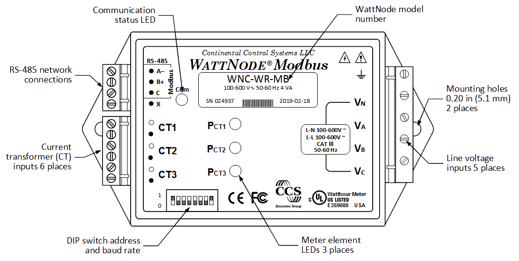
Diagnostic LEDs
Our diagnostic LEDs provide a per-phase indication of power (green flashing) and negative power (red flashing) to help troubleshoot connection problems, like reversed CTs, or excessive line voltage. The red/yellow/green communication LED indicates traffic, configuration problems, and other conditions. See the manual for full descriptions.
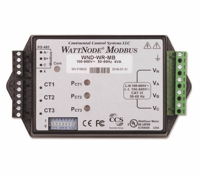
WattNode Wide-Range Modbus Overview
Specifications
Accuracy
- Nominal ±0.5%
- Meets the accuracy requirements of the ANSI C12.1 standard when used with CCS CTs rated for IEEE C57.13 class 0.6 accuracy (see Current Transformers Overview).
- Meets the ANSI C12.20-2010 class 0.5 standard for revenue metering with CTs when used with class 0.3 CTs (see Current Transformers Overview).
Electrical
- Nominal Operating Voltage Range: 100 to 600 Vac (line-to-neutral or line-to-line)
- Line Frequency: 45 to 65 Hz
- Minimum Operating Voltage: 85 Vac
- Absolute Maximum Voltage: 690 Vac
- Supply Watts: <2 W
- Supply Volt-Amperes: <4 VA
- Power Factor: 0.6
Current Transformer Inputs
- Voltage Mode:Nominal Input Voltage (At CT Rated Current): 0.33333 Vac RMS
- Absolute Maximum Input Voltage: 5.0 Vac RMS
- Input Impedance at 50-60 Hz: 23 kΩ
- Current Mode:Nominal Input Current (At CT Rated Current): 40 mA RMS
- Absolute Maximum Input Current: 200 mA RMS
- Input Impedance at 50-60 Hz: 10 Ω
Modbus Communication
- Protocol: Modbus RTU (binary)
- Baud Rates: DIP switch selected 9600 or 19200. Register configurable: 1200, 2400, 4800, 9600, 19200, 38400, 57600, 76800, and 115200 baud
- Address (ID) range: DIP switch selected 1 to 63. Register configurable: 1 to 247
- Duplex: Half (two-wire twisted pair with shield drain wire)
- Parity:Standard (default): N81 (no parity, eight data bits, one stop bit)
- Optional: E81 (even parity, eight data bits, one stop bit)
- Optional: N82 (no parity, eight data bits, two stop bits)
- Modbus Buffer: 256 bytes
- Response Time (typical): 5 to 25 milliseconds (may be longer immediately after a Modbus write command, while values are saved to non-volatile memory)
EIA RS-485 Interface
- Output Isolation: 4500 Vac RMS
- Driver Output:Voltage (Open Circuit): ± 6 Vdc maximum
- Voltage (54Ω load): ± 1.5 Vdc minimum
- Current (54Ω load): ± 60 mA typical
- Rise Time (54Ω || 50 pF load): 900 nS typical
- Receiver:Receiver Common-Mode Voltage Range: –7 to +12 Vdc maximum
- Receiver Sensitivity: ±200 mV
- Receiver Bus Load: 1/8 unit load (up to 256 WattNode meters per subnet)
Regulatory
- Safety: meets European Parliament Directive 2014/35/EU: Low Voltage Directive
- UL Listed (U.S. and Canada), file number E359088
- UL / IEC 61010-1, 3rd Edition
- CAN/CSA-C22.2 No. 61010-1-12, 3rd Edition
- FCC Class B, EN 55022 Class B
- EMC: meets European Parliament Directive 2014/30/EU: Electromagnetic CompatibilityEMC Requirements: EN 61326-1: 2013, industrial locations
- Radiated Emissions: CISPR / EN 55011, Class B
- Conducted Emissions: CISPR / EN 55011, Class B
- Electrostatic Discharge: EN/IEC 61000-4-2: (B) Self-Recovering
- Radiated RF Immunity: EN/IEC 61000-4-3: (A) NDegradation
- Electrical Fast Transient / Burst: EN/IEC 61000-4-4: (A) NDegradation
- Surge Immunity: EN/IEC 61000-4-5: (A) NDegradation
- Conducted RF Immunity: EN/IEC 61000-4-6: (A) NDegradation
- Power Frequency H-field Immunity: EN/IEC 61000-4-8: (A) NDegradation
- Voltage Dips, Interrupts: EN/IEC 61000-4-11: (B) Self-Recovering
- CE Mark and RoHS Declaration of Conformity
- Immunity: EN 61326: 2002 (Industrial Locations)
Environmental
- Operating Temperature: –40°F to 176°F (–40°C to +80°C)
- Altitude: Up to 9842 ft (3000 m)
- Operating Humidity: 5 to 90% relative humidity (RH) up to 40°C, decreasing linearly to 50% RH at 55°C.
- Pollution: POLLUTION DEGREE 2 – Normally only non-conductive pollution; occasionally, a temporary conductivity caused by condensation must be expected.
- Degree of Protection: IP40 (>1 mm solids, no protection from liquids)
- Indoor Use: Suitable for indoor use.
- Outdoor Use: Suitable for outdoor use if mounted inside an electrical enclosure (Hammond Mfg., Type EJ Series or equivalent) rated NEMA 3R or 4 (IP 66)
Mechanical
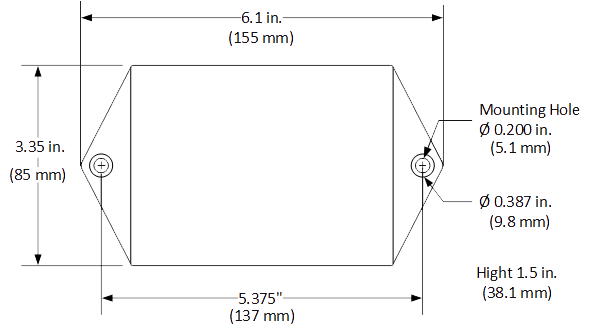
Case Dimensions
(Click on the image for a larger view.)
- Enclosure:
- High impact, ABS/PC plastic
- Flame Resistance Rating: 94V-0, IEC FV-0
- Size: 5.63 × 3.34 × 1.5 in. (143 × 85 × 38 mm)
- Weight: 8.2 oz (233 g )
- Connectors: Euroblock style pluggable screw terminal blocks
- Green: 22 to 12 AWG (0.32 to 2.5 mm2), 600 V, screw torque: 4.4 lbf·in (0.5 N·m)
- Black: 22 to 12 AWG (0.32 to 2.5 mm2), 300 V, screw torque: 4.4 lbf·in (0.5 N·m)
Modbus is a registered trademark of Modbus Organization, Inc.
Options
Many of the WattNode® Wide-Range Modbus® registers can be custom configured at the factory for an additional 10% programming charge. Meters with options cannot be ordered on line. Please contact our Sales Team at sales@ctlsys.com or call 303-444-7422 to request a quote or place an order for meters with options.
For more information about available options, see section 1.5 Options on page 7 in the Reference Manual (PDF, 82 pages) .
General Options
- Option CT=xxx – Pre-assign xxx as the global value CtAmps
- Option CT=xxx/yyy/zzz – Pre-assign xxx to CtAmpsA, yyy to CtAmpsB, and zzz to CtAmpsC
Communication Options
Unless otherwise specified, the factory default communications options are: no parity, eight data bits, and one stop bit.
- Option EP – Factory configure the Modbus RS-485 communications to default to even parity (E81)
- This can be field configured using the ParityMode register if you have meters that were ordered without this option and you need even parity this can be overridden or turned off in the field by changing the ParityMode register.
- Option 19K – Factory configure the RS-485 communications to 19,200 baud.
- This can be changed in the field by switching the baud rate DIP switch, or by writing to the Baud register. If you write “0” to the BaudRate register, then the DIP switch setting will control the baud rate.
- Option 38K – Factory configure the RS-485 communications to 38,400 baud. Position 8 of the DIP switch will be ignored.
- This can be changed in the field by writing a new value to the BaudRate register. If you write “0” to the BaudRate register, then the DIP switch setting will control the baud rate.
- Option AD – Factory configure the Modbus address.
- This can be changed in the field by by writing a new address to the Address register. If you write 0 (zero) to the Address register, then the DIP switch setting will specify the Modbus address.
Note: All WattNode Modbus meters can have their communication settings restored to factory shipped values by setting all DIP switch positions to “0” for ten seconds. If an communication option has been ordered, the meter will restore to include the settings from any options.
Meter Element Configuration Options
Configuration options are used to configure either the ConnectionType register (CTR) or the MeterConfig registers (MCR). Only one of these two options may be specified for a particular meter. See section 1.5 Options on page 7 in the WattNode Wide-Range for Modbus – Reference Manual (PDF, 82 pages) for more information.
- Option CTR=x – Set the ConnnectionType register to x (the default is 1).
| Connection Type | Name | Meter Element Mapping | Service Types | Notes | Meter Config1 | Meter Config2 | Meter Config3 |
|---|---|---|---|---|---|---|---|
| 0 | Custom | Custom | Any | May not be used with the CTR=x option | – | – | – |
| 1 | Wye | CT1-VAN CT2-VBN CT3-VCN | 3-phase 4-wire wye | May also be used for 4-wire delta service | 10 | 20 | 30 |
| 2 | Delta | CT1-VAC
CT2-VBC |
3-phase 3-wire delta | CT3 is not used. Works for grounded delta with any phase grounded. | 90 | 50 | 0 |
| 3 | Branch circuits | CT1-VAN CT2-VAN CT3-VAN | 1-phase, 2-wire with neutral | Use for monitoring 1-3 neutral connected branch circuits | 10 | 10 | 10 |
| 4 | House and Inverter | CT1-VAN CT2-VBN CT3-VAB | See notes | 1-phase, 3-wire with neutral for CT1 and CT2; 1-phase, 2-wire without neutral for CT3 | 10 | 20 | 40 |
| 5 | Line to Line | CT1-VAB | 1-phase, 2-wire (no neutral) | CT2 and CT3 are not used | 40 | 0 | 0 |
- Option MCR=xx/yy/zz – Set MeterConfig1 to xx, MeterConfig2 to yy, and MeterConfig3 to zz.
The mapping from current transformer inputs to line voltage inputs is controlled with the MeterConfig registers. There are one meter element and one configuration register for each current transformer. For each meter element (CT), you can select the line voltage to be associated with that CT from the following list:
- 0 = Disable meter element
- 10 = VAN (also called VA)
- 20 = VBN (also called VB)
- 30 = VCN (also called VC)
- 40 = VAB
- 50 = VBC
- 60 = VCA
- 70 = VBA (equal to -VAB)
- 80 = VCB (equal to -VBC)
- 90 = VAC (equal to -VCA)
The default settings for the MeterConfig registers follow. These match the behavior of the older WNB and WNC meters:
- MeterConfig1 = 10
- MeterConfig2 = 20
- MeterConfig3 = 30